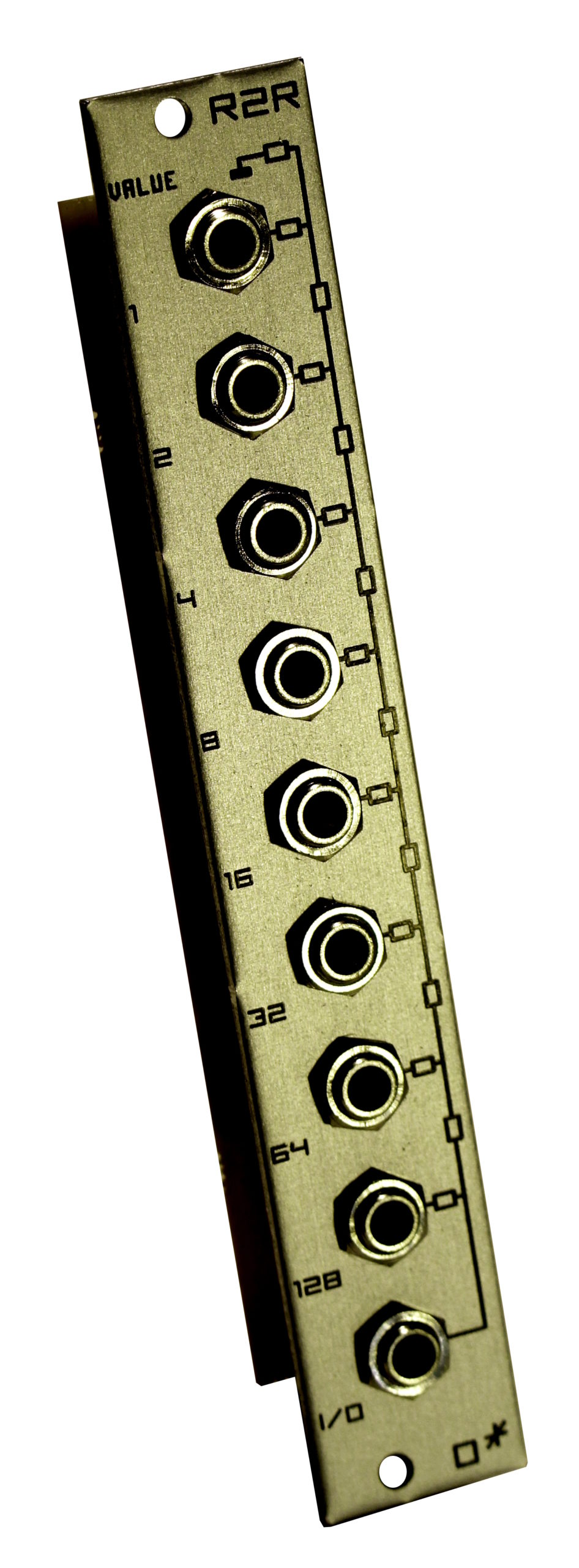
Olegtron R2R
£32.00
Out of stock
Description
R2R – multi-function passive utility module
R2R continues Olegtron’s line of simple instruments capable of messing things up big time. Let’s start with the simplicity of it’s electronics. For mayhem, please scroll down.
The electronics inside R2R isn’t a circuit by definition, rather a string of resistors with another set of resistors branching from the string, connected to jacks. The other end of the string is grounded, the other end and the branches are freely floating. The artist’s impression below captures the nature of the module: the jacks close to ground are less floozy, the ones above are more likely to go with the flow.

So what’s going on with the resistors? Resistors are electronic components that resist the flow of electrons, e.g. electric current. This property is called resistance, and the unit is ohm, ᘯ. If the resistance is small, electrons flow easily. Large resistance makes it more difficult for the electrons. The resistors inside R2R are fairly large, 10kᘯ and 20kᘯ (10 000ᘯ and 20 000ᘯ).
You can find more info on resistors from the web, so let’s concentrate on Olegtron R2R. The first principle is, that when you connect a signal to any of the jacks, it affects the voltages in all the other jacks.* The ground connection has got a kind of a stabilizing effect, since the jacks near to ground are connected to ground with a smaller resistance. As more resistors are added to the series, the ground connection gets more distant. So, a signal plugged to a jack near ground has less overall effect compared to a signal plugged further from ground. Same principle goes when you plug more signals in: the signals get mixed together in relation to each other and the distance to ground. That’s how inputting signals work.
If you wish to get some signals out of the module, they’re available all around the place: the unused jacks provide each a different mixture of the signals, according to how near the signals are to each other, and to ground. The signals plugged to jacks near to the output are emphasized in the mix, and the output level is likely to be smaller when taken from near the ground.
The jacks are always connected to each other (or to ground) through at least a 20kᘯ resistor, so it’s not possible to short-circuit signals. This means it’s safe to connect any signal (input or output) to any of the jacks.
* Except when you use the I/O jack as an input, the signal gets basically multiplied to jack 128, so there’s no change in voltage. Signals input to the other jacks don’t have effect on the signal at 128 and I/O in this case.
Practical circuits
As mentioned before, when not connected, the module is just a set of resistors. However, different circuits are formed when you connect signals in and out. Very basic resistor math comes handy in here: when two or more resistors are connected in series, their values are simply added together, and the unused resistors don’t have any effect.
The image below illustrates the internal schematic of the module, and a couple of examples of the practically unlimited amount of different circuits that form between the jacks being used. In every connection some voltage dividers are formed. Voltage divider outputs the input signal at a scaled down voltage, according to the ratio of resistors in it. Note that when used as outputs, jacks 1 to 128 have a 20kᘯ series resistor, or in other words, output impedance added. There is an on-line simulation of the three circuits here (The simulation needs to be run in a Google Chrome browser).

8-Bit Digital to Analog Converter (DAC)
The traditional function of a R2R-network is to convert parallel digital signals to stepped analog voltages. Digital signal means in this context a signal that has got two states, LOW and HIGH, represented by two voltages, such as 0V and 5V or 0V and 8V. Eurorack modules that output gate, clock or other logic signals qualify as digital in here. If you want linearity, the input signals should be equal in voltage levels. It’s not necessary by any means, though. The conversion will just be biased if the signals are of different amplitude.
When used as a DAC you connect digital signals to the jacks named 1-128 (according to the binary values), and the resulting analog signal is output from the I/O jack. However, you can output a signal from any other unused jack too. The linearity might not be ideal, but you get different results since all the jacks work differently: by selecting the output jack from nearby ground results in more subtle changes in voltage, etc.
You don’t have to use all the inputs, and you can freely experiment with different combinations. The GIF below shows a simple case where a clock divider is used as the source of digital signals. In the example there are 24 possible routings, which all result in a different sequence, or wavetable when used in audio range. Hot tip! Use Olegtron Confusor or Confusor 2 to change between different routings!

The resolution, i.e. the amount of steps, depends on how many bits are used. With 1 bit you get 2 different voltages, with 2 bits 4, with 3 bits 8, etc. Olegtron R2R has got 8 inputs, (8-bit like your old Nintendo, huh?) so the maximum resolution is 256 steps when all the inputs are used. Please note! Since the range starts from 0, the largest value is always one step away from the maximum. Below is a summary of the 24 permutations you get wit 4 bits.
An on-line simulation of the working principle can be viewed here (Chrome only). You can switch on and off signals by clicking on the switch symbols.

How does R2R work as a DAC in practice? In the basic configuration you plug a cable from R2R I/O-jack to a CV input of another module, such as cutoff frequency of a filter, pitch of an oscillator, input of a quantizer etc. Then you continue by plugging signals to the other jacks.
The signals can also be from different kind of dividers (4ms RCD plays really well along, specially when you feed back one of the R2R signals to Rotate input), sequencer gate outputs, logic modules etc. Instead of thinking of the bits, you can just experiment: if the signal does not have a desired effect, just change it to another jack. If you use R2R in generating melodies, and want to fit the output to a certain scale, you might want to try different outputs, use a quantizer, CV-processor, or an attenuator to find proper notes.
After you have the CV sequence going, you might want to try and add some other signals to some unused inputs. The signals will add to the mix depending on the chosen input. Plugging an LFO to one of the jacks creates a vibrato to the sequence, etc. If you wish to have more attenuation, please look at the bottom of the page.
8 Channel Weighted Mixer
There is no difference between using the module as a DAC or as a mixer, they’re both the same. Maybe it’s just more convenient to talk about a mixer when you use the module with other than digital signals. And the module does accept other signals, AC/DC, you name it.
Unlike most mixers that use knobs or sliders to adjust levels, R2R mixing is done by choosing different inputs: 1 is the quietest (lowest voltage), 128 the loudest (highest voltage). That’s why we call it weighted. Since there are no knobs, the footprint of the module is small for an 8 channel mixer. In addition to saving space, being knobless makes it easier to redo a patch with exactly the same values.
Another thing separating R2R from other mixers is the ability to use many different output signals at once. Again, if you wish to have more attenuation, please look at the bottom of the page.
Programmable Attenuator
Derived and simplified from the modes above, you can also use the module as an attenuator, or a voltage divider to be precise. In this mode you use the I/O jack as the input, and the other jacks give out different voltages divided from the input voltage. The following image shows the ratio of voltages:

As you probably guessed, you can use any other jack as the input, as long as it has got a higher number than the output. Two different voltage dividers are illustrated in ´Practical circuits´. If you wish to have more attenuation, please look at the bottom of the page.
Labile Duplex Multiple
As the image above shows, signal input to I/O gets pretty much multiplied at jack 128. There is only a 20kᘯ impedance added there. This is the closest to absolute the whole module will ever get, and will come in handy at routing a signal without a drop in voltage through the module, while being able to use the signal in the mixture of the rest of the R2R at the same time.
Also inputting a signal to a jack with smaller number and outputting from ones with a higher number more or less splits the signal. More or less that is. The module is labile by any standard.
Oh, and when using R2R as an attenuator. you can use multiple outputs (each has a different voltage) to control multiple CV inputs. For example controlling the pitch of multiple oscillators with different voltage divisions of the same signal results in lively harmonic intervals and chords out of the ordinary. Don’t hesitate inputting another signal to the soup, since we’re rapidly approaching the final chamber the…
Goofproof Whatever Station
Combine (or then just forget) everything you have learned about the R2R and just patch stuff in and out! You can freely use any jack to input and output signals in both directions. When you input more than one signal, they get mixed, attenuated and split in various ways. The thumb rule is that jacks near to each other have more influence on each other.
Disclaimer
That all being said it’s evident that the function of the module is not absolute in any mode, and everything affects everything else. In return the module is safe to use in any fashion. All the jacks are interconnected by resistors, and there is at least a 20 kilo-ohm resistance between any two jacks. These resistors make it safe to patch input and output signals simultaneously without short-circuiting them. The resistors in the array have a manufacturing tolerance of +/- 2% in resistance, thus limiting the maximum precision.
Extras
Since the module’s architecture is open, the jacks are floating when unconnected. This means, that the only attenuating element is the ground connection at the other end of the string. If you want more attenuation, connecting some more jacks to ground does the trick. Think of it as bringing 0 volt DC signals to the mix, calming things down by the weight of the input jack. You can do this by connecting a jack to an output of any digital module, that’s in LOW state, or, say, an envelope in the “resting” state. Anything with zero volts. Also, connecting any other static signal will work the same way, only pulling the signals toward the signal’s voltage by the weigh of the input.
Acutally, having all inputs in LOW state is the common starting point of a DAC: the output voltage is reliably zero when all the signals are LOW. Also, when all the signals are connected to either HIGH or LOW (not floating), the jack numbers do actually correspond to the weight they have in the conversion
The jacks are floating by design choice, but they can be normalized to ground by connecting certain solder pads, see the modification below. With our choice of configuration, though, there’s more freedom and less attenuation in the module, and it behaves better when patching: if the jacks would be normalized to ground, plugging a cable to one of the jacks would break the normalization, and might make an undesirably large difference in signal levels.
Any ways, it’s a matter of opinion and usage, which way of connecting the jacks works best for you. The modification below goes to jacks 1-128, but you can use the same principle with I/O jack as well, for even more attenuation. If you don’t want to modify the unit, there are other choices further down the page.
Olegtron R2R official modification: Normalizing the jacks to ground
The modification is super simple, and requires just two small pieces of wire (component legs will do just fine) and a little bit of soldering. The idea is to ground the 8 pads that lead to the normalize terminal of the jacks. The picture below pretty much sums it up. Please note, that you don’t necessarily have to ground all of the jacks – grounding jacks from 16 to 128, for instance, is a nice compromise, leaving jacks 1 to 8 floating.

“R2E” – Expander for Olegtron R2R
You can also wire the 8 solder pads to an expander panel with 8 switches, each for grounding one jack. Below is an example drawing of the expander, using a 4HP eurorack panel and some common SPDT toggle switches.
Plugs
Another fun project is building custom plugs with tip and sleeve connected by a wire, or recycling the plug from a broken cable by cutting the cable short, peeling the wires and soldering the ground and signal wires together. When plugged in the shorting plugs will accomplish the grounding discussed in the two modifications before.
While you’re at it, go ahead and make some plugs with components too. Start by connecting, say, a 10uF capacitor between tip and sleeve, and you will get a slew limiter (glide) effect depending on the jack you plug the capacitor to. Experiment with different values and different components. Since some other modules might not like experimental loading of their outputs, it’s probably wise to use the add-on plugs only with Olegtron R2R.
Downloads
You can download this webpage as an PDF for offline reference here: Olegtron R2R documentation.pdf

