Olegtron 4060MK2
£116.00
Out of stock
Description
A standalone sound generator or control voltage (CV) signal generator
Olegtron 4060, originally released in 2013, has been updated to a MK2-version. The semi-decennial celebratory release, altough wearing a new colorful plumage, is pretty much the same machine inside. This means that the tutorials and demos will serve to the users of the 500+ original units, as well as users of the new one. Many improvements have been made, though – thanks to feedback from users of the original version. Some requested features could not be included in the new design, but let’s see if a MK3 version will emerge one day! Here is the list of new features:
-
Four 3,5mm TRS stereo connectors for a maximum of 8 signals in/out
-
Large color coded patchboard
-
Changeable patchboard elements: if the patchboard becomes loose, you can change the connector elements to fresh ones
-
Integrated 7-bit saw generator: buffered saw and ramp outputs
-
Power input socket: a standard 2,5mm center positive barrel type power jack.
-
Power LED to make sure you will not leave power on accidentally – the LED also starts to flicker when battery is weak
-
Buffered virtual ground
-
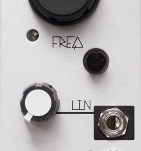
”Link sleeve”-jumper in the front panel for setting the working range:
-
Link to – (battery minus) for unipolar 0-9v range
-
Link to G (virtual ground) for bipolar +/- 4,5v range
-
-
Trimmer for setting the working range of FREQ-potentiometer in the front panel
-
A socket in the front panel for adding a frequency capacitor
-
Bigger knobs for better precision and comfort
General information
So, what is Olegtron 4060? It’s a compact oscillator / frequency divider box capable of creating signals and sequences through a revolutionary programming method: sticking electronic components to it’s patchboard! The device can be used as a standalone sound generator or as a control voltage (CV) signal generator to a wide variety of machines, such as modular synthesizers. When used as a CV-generator 4060 can easily deliver complex results that would normally need a large system.
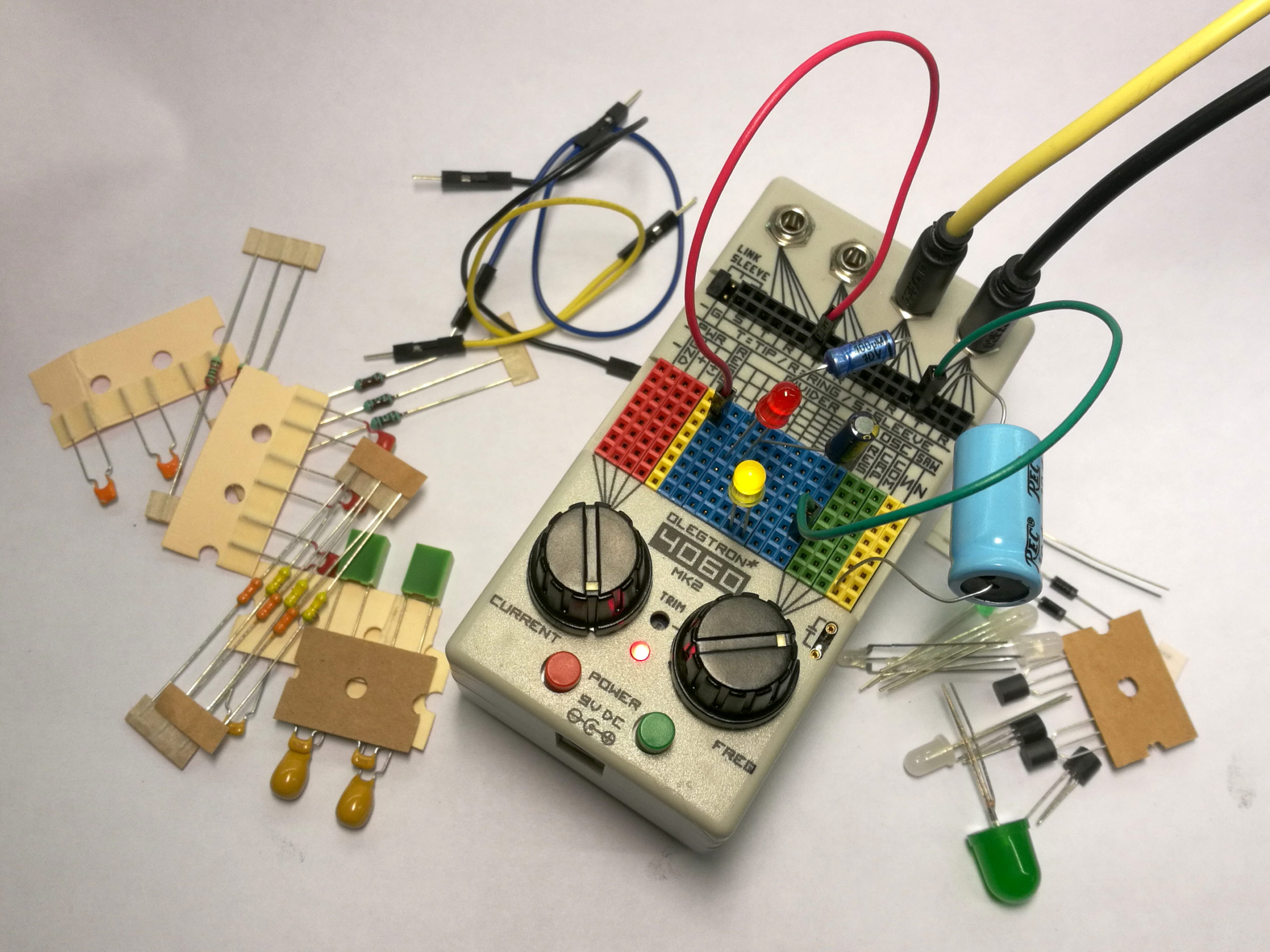
Learning the 4060 is easy, but there is a lot to master. Using it doesn’t require any previous electronics skills, but experimenting with different electronic components helps you get the idea how they work, and your programming can become more systematic. The provided resistors and small capacitors are color coded for clearness.
The name of the device comes from CD4060, which is an integrated circuit, a “chip”. It belongs to a series of CMOS logic chips called 4000B and interfaces with other chips of the series seamlessly. The series dates back to the sixties, but is still relevant in sound electronics and DIY. The CD4060 contains an oscillator with adjustable frequency and a frequency divider, that outputs 10 different subfrequencies.
Olegtron 4060 is based on an RC-oscillator example from the CD4060 datasheet, with the addition of a current limiting potentiometer that kind of simulates a weak battery. The rest is mostly user interface design, highlighting of course the innovative patchboard that makes a good playground for experimenting.
Olegtron 4060 MK2 ships with a bag of components to get started with. All you need is a 9v battery or a 9 volt wall wart, and something that connects to a 3,5mm headphone jack.
Uses
-
Stand alone sound generator: plug into your amp or headphones (start with low volume!)
-
Synth control: send CV, clock and gate signals to your synth and from the synth to 4060!
-
Circuit bending: trigger toy buttons, modulate pitch and more…
-
DIYer’s test signal generator
-
Sound manipulation: feed amplified signals to 4060 and output them with a no-fi flavor!
-
Light sequencing: connect single- or multicolored LEDs straight or via a driver
-
Combine above uses and keep everything in the same fluctuating sync
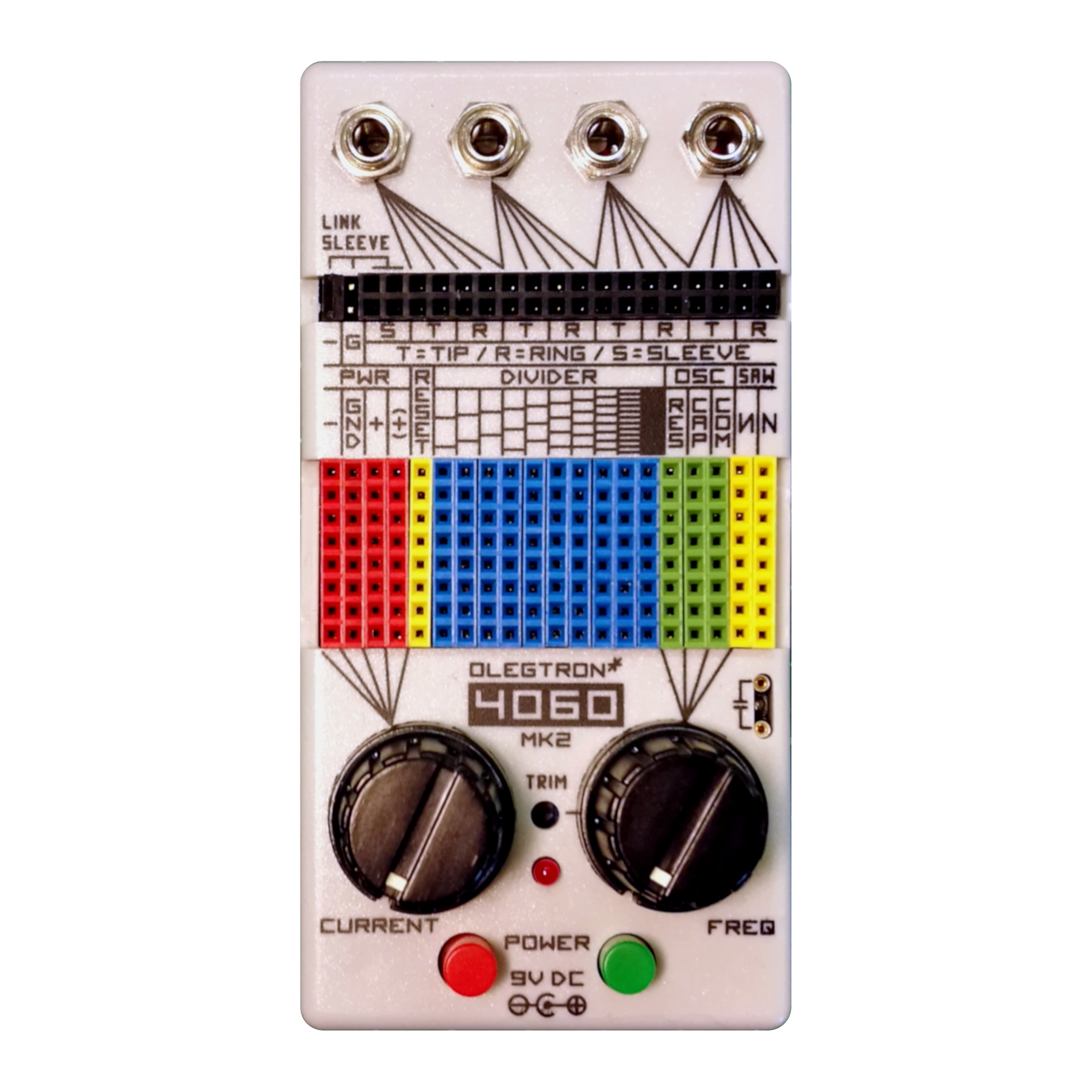
Anatomy of Olegtron 4060 MK2
Here’s a brief introduction to different sections of the 4060 MK2. The text and images are roughly the same as in the paper shipped with the device, and will be updated along the way. You can find the papers in pdf format in the bottom of this page. These matters will also be discussed in forum, so please log in and share your thoughts!

I/O-section consists of four 3,5mm TRS-connectors, which are used to feed signals to and from 4060. When nothing is patched, no signals are connected to the connectors! You can patch any patch point to the connectors with jumper wires or with components! TRS refers to Tip, Ring and Sleeve – the connector is best known from headphones. The connector is stereo, so you can use it to transport two signals. Tip usually connects to left channel, ring to right channel and sleeve to signal ground.

You can connect the LINK SLEEVE jumper in three modes: a. “Link to –“ will make the device appear as unipolar, with signal swing from 0 to 9 volts. b. “Link to G” will link SLEEVE to virtual ground making the device appear as bipolar with +/- 4,5v range. This mode is suggested when connected to Eurorack or other synths. In this mode the device also reacts more easily to incoming signals. c. If you disconnect the jumper you can patch a third signal to SLEEVE. In the last case the signal connected to SLEEVE will “bounce” the ground up and down, thus affecting all of the possible 8 signals in the 4 connectors. In this mode the signal swing is +/- 9v, meaning 18 volts peak to peak!. Which brings us to the fact, that before connecting Olegtron 4060 to another device, make sure that the device can stand the voltage!
Please note! If you use a mono plug, the connector’s RING connects to SLEEVE. When using a mono plug, signal is connected to TIP.

PWR-section is what makes the CD4060 chip behave in a more interesting way. Adjusting the CURRENT knob limits the amount of electrical current provided for the chip, as would happen with a weak battery. When the current is not adequate, the efforts made by the chip – oscillating and dividing – start to show as instability. Add components to the patch board and you can hear how they load the circuit, each in a different way. If the device halts, dial the CURRENT up or remove the last component.
Battery voltages are available in – and +. In the MK2 version there is also a buffered virtual ground, GND, which gives out a voltage in the middle of the operating voltages. More info in the I/O-section. The limited, i.e. starved, voltage is available in ST+. You can use ST+ as a kind of a general output of the device’s inner workings.
There is a 180 ohm resistor in series with the power supply, meaning that the system never gets full power. As a result of this you cannot get an absolute clean signal from the box. On the positive side the resistor makes it safe to plug components around the patch board. It is advisable however to check capacitor polarity and voltage rating before patching to PWR-section.

DIVIDER-section provides the nominal outputs of the CD4060 chip. But worry not! In case of Olegtron, the outputs can be used as inputs too, sensititvity depending on the setting of CURRENT and the components used. This is also a good area to start plugging components to alter the sound.
In divider there are 10 divisions derived from the oscillator base frequency. In audio range the outputs are perceived as different octaves of square wave signal. In low frequency range the signals at the outputs appear as voltages changing state between high and low, each output at half the tempo compared to the previous. Please note that for some reason there is a one octave gap, i.e. a subdivision missing before the lowest three DIVIDER outputs.
When you input a positive signal to RESET input, it will reset all DIVIDER outputs to low state and stop the base frequency oscillator. When the signal at RESET input goes back to low, oscillation starts again and the divider begins to count. If you want the reset input to only briefly reset the outputs, and keep the oscillator and divider running, use a small capacitor for patching!

OSC-section gives you access to the base frequency that affects the pitch and tempo of the whole system. The frequency is adjusted by turning the FREQ knob. By adjusting TRIM with a small screwdriver you can limit the frequency range and look for sweet spots at the upper threshold where oscillation just barely happens. In the original version TRIM potentiometer is situated inside the box.
You can also use external components to control the frequency: If you want to speed up the oscillator, patch a resistor between RES and COM. Hot tip! Try an LDR for light/gesture control! If you want to slow down the oscillator, patch a capacitor between CAP and COM. The metal sockets next to the knob double the CAP and COM, so you can patch a capacitor there for more permanent slowing. These sockets are inside the box in the original version.
You can also output signals from the OSC patch points when you need high pitched sounds. The waveforms in OSC section are also different if you need a change of timbre. Since we are in the center of the action here the OSC, the patch points are quite sensitive. So, if the oscillation stops, try patching with a large resistor or some other component to avoid loading the oscillator.
Since the OSC section is so delicate and vulnerable, you can feed external signals into the patch points to sync/override the internal oscillator. Try linking SLEEVE to GND (see mode b. above) and adjust CURRENT for better response. You can also patch signals from 4060 itself for some internal modulating. Start with a small capacitor from DIVIDER to RES.

SAW-section integrates the popular “7-bit saw” module of the original 4060. It’s now buffered and inverted, though. The SAW section takes 7 of the highest DIVIDER frequencies and converts them into a rising sawtooth wave, and it’s mirror image. The waveforms are far from ideal, but provide a different timbre/good starting point for an LFO. When you patch components to the patch board, the SAW-waveforms will change.

POWER switches are wired in a three way configuration: The red one is used as an on/off switch, and the green one changes the state momentarily: off > on and on > off.
The power LED shows the state of power, and will get dimmer and start to flicker when battery is about to throw in the towel.
You can also use a wall wart to power the device. When you plug in an external power adapter, the battery gets disconnected. The nominal voltage is 9v, but the device will work with voltages from 3v to 15v. When using larger voltage input, the device also outputs larger voltages!
Chronicles of Olegtron: The 7-bit Saw-module
Since march 2016 all original Olegtron 4060 units have shipped with a plug-in module called ”7-bit Saw”. The plug-in module works as a D/A converter, turning 7 of the highest frequencies of 4060 into a stepped (128 steps) sawtooth waveform. The module gives you another timbre, but makes getting started easier too: you don’t have to patch any components to get a sound out!
All you have to do is plug the module in and the sawtooth is output straight to the TIP of 4060’s TRS-connector. Just connect a normal 3,5mm mono patch cord and get the signal to your system with unprecedented ease! If you use a stereo cable, you can patch another signal, input or output, to the RING, as you would normally do with the 4060.
Patching the 4060 with electronic components works pretty much the same as normally. Adding components causes fluctuation in the waveform, but instead of squarewave, the basic waveform is sawtooth. If you want low frequencies, like a rising CV-sequence, place a small capacitor between OSC: CAP and COM. The pictures below illustrate the waveform with and without components.
7-bit Saw is now integrated to 4060 MK2, accompanied by an inverted “mirror image”.

Downloads
4060 MK2
Olegtron 4060 MK2 Introduction and component set (pdf)