Digital VCA
£165.00
2 in stock
Description
(Voltage Controlled Attenuator)
This is a novel module with a few bells to enhance your modular experience. It uses a digitally controlled analog circuit that allows for some creative control!
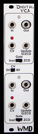
The rubber hits the road on this module with the Instant / Gate / Zero Crossing Detector switch and CV input. Normal operation happens in the Inst mode where the VCA will follow the CV signal as it is seen.
Things get more interesting when you enter Gate mode which causes the CV to be updated ONLY on a rising edge of the signal going into the Update G/ZCD jack. This jack has the In jack’s signal normaled to it. Gate mode allows the Digital VCA to sample and hold a control voltage, very useful for pulling modulation data out of other sources. This mode uses a Schmitt trigger to ensure noisy signals can be used without causing multiple unintended updates.
The Zero Crossing Detector is the crown jewel of the Digital VCA. This little circuit only allows the VCA to be updated when the Input signal (or Update G/ZCD signal) is at 0 Volts. This eliminates popping and clicking normally associated with fast envelopes. It allows you to use a Gate signal directly as an envelope without annoying pops!
WMD would like to thank Suit & Tie Guy (STG Soundlabs) for the concept. STG Soundlabs will be releasing a 5U/MU format version of the Digital VCA.
Features:
- Dual VCA Design
- Low Distortion / Low Noise
- VCA Closes Completely
- Zero Crossing Detector
- Gate/Trigger Detector
- 5V/8V CV ready
- 8 bit CV resolution
- Analog Signal Path
- Bi-Color LED Signal Indicator
- Red CV Indicator
- 6 HP
- Great for Ultra Fast Envelopes
Controls and I/O:
Input – This DC coupled input handles control voltages and signals up to 20Vpp in amplitude.
CV – Insert your control voltage here. Designed for 0-5V or 0-8V signals. CV strength will appear on the red LED above this jack. 5 or 8 V produces unity gain on the output. Exceeding these voltages or using negative voltage will not damage the device.
Update G/ZCD – This input controls the updating in Gate and ZCD modes. In Gate mode, the rising edge will cause CV to be updated. In ZCD mode, the signal must be at or crossing the 0V potential (ground) for CV to be processed.
Output – Attenuated signal output.
CV 5V / 8V Switch – This slide switch controls whether the VCA expects to see 8 Volts or 5 Volts at the upper limit.
Inst / Gate / ZCD Switch – This switch controls the operating mode of the Digital VCA. Instant mode continuously updates from the CV input. Gate updates on rising edges of the signal on the Update G/ZCD jack (normaled from the Input). ZCD mode updates on zero crossings.
Specification:
- The Digital VCA is 6 HP.
- Current consumption is 75mA for the +12 rail; 45mA for the -12 rail.
- The depth from the back of the panel is roughly 31mm.