Sequential Switch Matrix
£350.00
Out of stock
Description
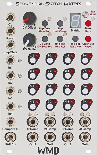
4×4 triggered/CV addressed routing matrix
(Rare NOS – last few available)
Four inputs can be routed with individual buttons to four outputs. Those routing settings are stored in an array of matrices that can be sequenced or controlled with CV. Preset routing, feedback loops, chop sequences, trigger blasts (with expander), four-bit-wavetable-synthesis, and dramatic controllable mayhem are all possible.
- Four inputs can be routed individually to four outputs
- Saveable routing matrices for a variety of effects
- Controllable via sequencer or CV
Expander module – SSM Expand
The signal path uses 0.1% resistors and will pass precision pitch or other CV signals with minimal gain and offset errors.
Inputs 1 – 4: These inputs accept bipolar +-10V signals before clipping. Signal level will illuminate the adjacent LED; green for positive voltages, red for negative.
Outputs 1 – 4: These outputs (along the bottom) contain the signals from the inputs (summed together) if the routing LED is lit.
Comparator: The Compare In input voltage is compared to each output voltage. If the output is higher than the Compare In voltage, the Comp output will be high (10V gate) for that channel. The blue LED will also be illuminated.
DAC 1:2 Out: This output is generated from the status of the first two columns. It is a weighted Digital to Analog conversion. 1-1 is the most significant bit, carrying a weight of 2.5 volts. 2-1 is exactly half that weight (1.25V). 4-2 is the least significant bit (0.020V). The two columns provide an 8 bit voltage output that is always present.
Routing Buttons: Tapping the routing buttons will toggle its state. If a button is pushed, it will change for that matrix only. Push and hold has no effect on routing buttons.
Matrix: The current matrix is displayed on the numerical display. It will read 0-9 then A, B, C, D, E, F to represent the 16 matrices in hexidecimal.
Bank: Tapping the Bank button will change banks. LED off is bank 0. Green is bank 1. Red is bank 2. Orange is bank 3. All settings (except for Rnd Rcl) are stored with each bank.
Save: Push and hold to save all banks, matrices and modes to the internal non-volatile memory. Powering down without saving will revert to the last saved settings.
Top: The top matrix will be the reset point when stepping. It is indicated by the decimal point on the Matrix display. Tap the “Top Set” button to set the top to the currently selected matrix. Push and hold (Top Clear) to clear the top, which will step through all 16 matrices.
CV Limit: When the LED is off, CV acts as an offset that can go beyond the Top. When the LED is Green (tap “CV Limit”), the CV is limited to the top, so the CV will be clipped to the Top Matrix.
CV Sets Top: Indicated by the LED being red. The CV will set the top matrix. This allows for CV control of the Top matrix, or CV control over the length of the sequence. CV will no longer change matrices in this mode.
Step Down: When the LED is off, gates and the Step button will step up. When the LED is green, gates and the Step button will step down.
Gate Rnd: Indicated by the LED being red, Gates (only, not the step button) will output a random matrix within the specified Top.
Step: Tapping will step through the matrices.
Hold/Slave: Indicated by the LED being red, this mode stops any CV or Gates from incrementing the matrix counter. You can still step through the Matrices with the buttons, as well as change modes.
If the Macro Machines Memory Manager is connected through the bus board, the SSM will listen for MIDI Control Changes and any received signals will change matrices. When a signal is received, the SSM will slave completely, and can only change matrices and banks from MIDI Control Change.
Clear Mtx: Tapping this will clear the matrix and any I/O connections.
Reset: Push and hold to reset the matrix counter to 0. Remember that CV is not part of the counter and can still offset the matrix that is output.
Rnd Mtx: Tapping this will randomize the currently selected matrix.
Rnd Rcl: Push and hold to light the red LED. When lit, the currently selected matrix will be randomized every time it is recalled via CV, Gate/Step or the Step button. This mode is stored with each matrix.
CV Input: The CV input is attenuated by the CV Scale knob, and added to the CV Offset control.
Step Input: This Trigger input will step the matrix counter depending on the modes set by the buttons per bank.
Reset Input: This Trigger input will set the matrix counter to 0 if counting up, to F if counting down.
Step and Reset are trigger inputs, the rising edge is detected, and the input must fall before another trigger can be detected.
Specs:
- Power: +12V = 80mA; -12V = 32mA
- Width: 16HP
- Depth: 25mm

