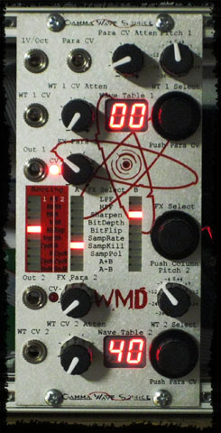
Gamma Wave Source
£260.00
Out of stock
Description
The WMD Gamma Wave Source is a dual digital wavetable VCO that can create millions of timbres using onboard digital “effects”.
The Controls
1V/Oct – Pitch input, used with standard 1 Volt per Octave keyboards and MIDI-CV converters. 0-5 volt input.
Pitch 1 & 2 – Controls the relative pitch per channel.
WT 1 & 2 Select – Select the desired wave table from the chart. 256 are available, each producing a different sound. Click for the table chart.
Out 1 & 2- Oscilator section output, each puts out +-2.5V/ 5Vpp signal.
The Effects Section
The GWS has four effects pipelines. Two for each oscilator. The Routing table selects how the oscillators interact with the effects pipelines.
FX Select Knob – Pushing this knob in will select the column that the knob is adjusting. Turning it will adjust the LEDs in the select column and will alter the Routing or Effects selection.
FX Para 1 & 2 – These knobs control the FX parameter for the oscillator section. Each effect has a specific parameter that is controlled by this knob. Adujust to taste.
Para CV & Attenuation Knob – This is a CV input for modulating and controlling the effects on the oscillator. Press the WaveTable Select knob to activate CV control per oscillator section. The LED will light when CV control is active. The FX Para knob will adjust the center or edges of the CV control depending on the selected effect.
Effects Table – These are the available effects, they are all created mathematically using 8 bit processing. The result is generally lo-fi and edgy, but smooth fat sounds are also possible.
LPF – Digital low pass filter, mellows out tone
HPF – Digital high pass filter, removes lows for brighter tone
Sharpen – Similar to HPF, but more aggressive
Bit Depth – Reduces vertical fidelity of signal
Bit Flip – Collapses signal in on itself, adds harmonics
Sample Rate – Reduces horizontal fidelity of signal
Sample Kill – Kills samples at a rate set by Para knob.
Sample Polarity – Inverts the signal at a rate set by Para knob
A+B – Adds the OSC1 and OSC2 wave tables and outputs
A-B – Subtracts the OSC1 and OSC2 wave tables and outputs
Routing Table – The routing table is depicted by the red rectangle. If no LED is lit, then effects are bypassed entirely.
A | B – OSC 1 -> FX A | OSC 2 -> FX B
AB | BA – OSC 1 -> FX A -> FX B | OSC 2 -> FX B -> FX A
AB | B – OSC 1 -> FX A -> FX B | OSC 2 -> FX B
A | BA – OSC 1 -> FX A | OSC 2 -> FX B -> FX A
AB | Byp – OSC 1 -> FX A -> FX B | OSC 2 -> No FX
Byp | BA – OSC 1 -> No FX | OSC 2 -> FX B -> FX A
CycA | B – OSC 1 -> Cycle forward through FX A | OSC 2 -> FX B
A | CycB – OSC 1 -> FX A | OSC 2 -> Cycle reverse through FX B
CycA | CycB – OSC 1 -> Cycle forward FX A | OSC 2 -> Cycle reverse FX B
RndA | RndB – OSC 1 -> Random FX A | OSC 2 -> Random FX B
When cascading effects (Osc 1 -> FX A -> FX B) the first effect in the chain has its parameter set by the FX Para knob ONLY in the top routing mode (A|B). This is then saved so that the tone can be retained during cascading.
Cascading Sequence – Properly cascading effects requires this process:
Set routing to (A|B)
Set first effect in chain and adjust parameter to taste
Set routing to cascaded mode (AB|B)
Set second effect (FX B) to taste using FX Para knob
Adjusting the wave table will retain parameter settings for the first effect in the chain.
Calibration
The modules are calibrated at the factory, but may require slight adjustments to adapt to your MIDICV converter or CV keyboard and power supply. The steps below are for full calibration. To enter calibration mode, push and hold the FX Select knob while powering on. “cA” will appear on the upper display.
Monitor the audio on OSC1. Turn the FX Select knob CW until the top LED is lit. Start with the lower Trim Pot fully clockwise. Set input on 1V/Oct to C#0 (~.166V). Turn the lower Trim Pot counterclockwise until C#0 is heard and “01” is seen on the upper display. Turn just a little past the transition point.
Then set the CV source to B4 (~5V). Turn the upper trim pot until B4 is heard and the display reads “3B”. Clockwise adjusts downward.
Check calibration by playing each note from C0 to C5, if any note is shaky; repeat adjustments until all notes play properly. Start with slight adjustments to the upper trim pots.
Turning the FX Select knob will show the input parameters for the module on the screen. In order going down: 1V/Oct, Pitch 1, Pitch 2, FX Para1, FX Para2, WT CV1, WT CV2, Para CV, Fine tune.
To Fine Tune – Set The FX select knob CycA/CycB in Calibration Mode. Turn the FX Para 1 knob to fine tune the oscillator. Use a tuner or other reference and adjust FX Para 1 until set. When done, turn the FX Select knob so that “cA” is on the upper display and wait 10 seconds for setting to be saved.
Specification:-
- 256 Wavetable Modulator
- Top Quality Components
- Anodized and epoxy screen printed
- Standard 10pin Eurorack Cable
- Current Consumption:74mA on +12 and 11mA on -12 rails
- Panel size: 12HP