Description
Basic features
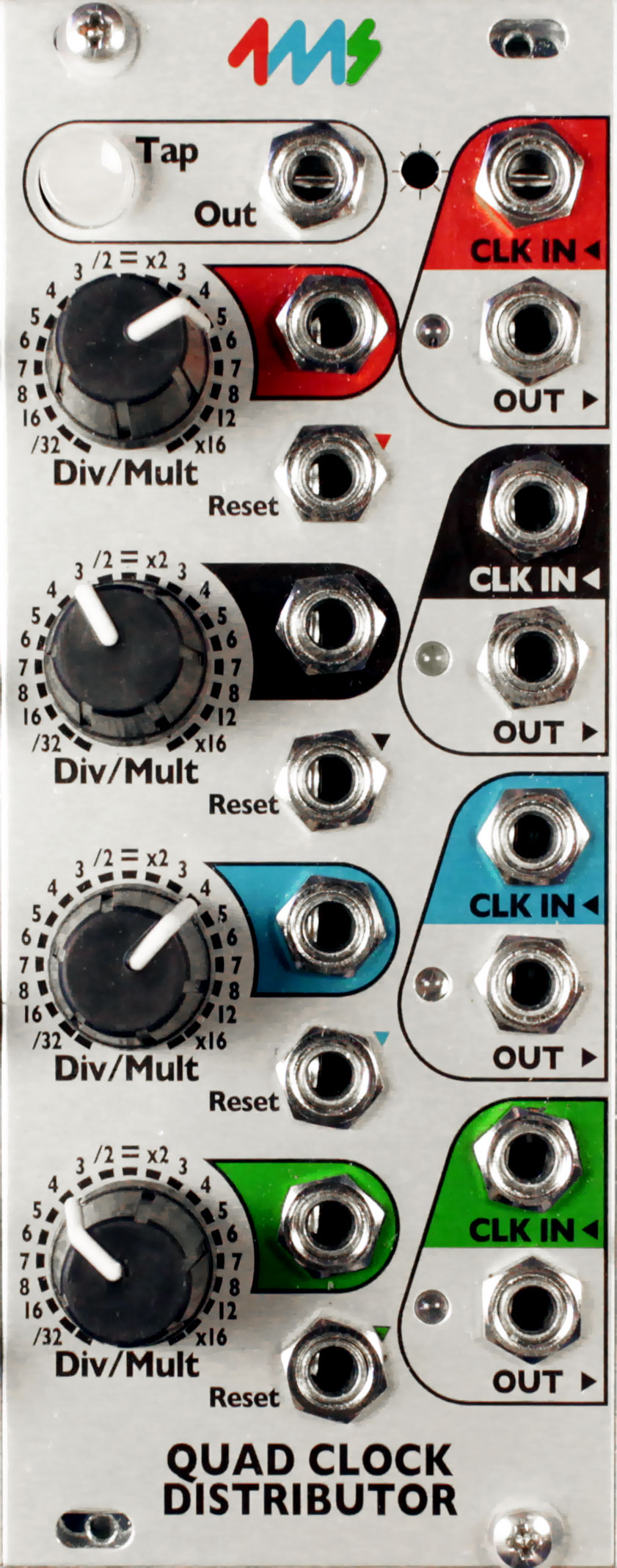
- Four CV-controlled Clock Divider/Multipliers
- Tap tempo button and five sync’ed clock outputs make the QCD perfect for head-of-the-chain “Master” clock module
- Tap clock output runs at the tapped tempo (even if other channels are being clocked externally)
- Create complex rhythmic patterns by patching multiple channels into each other’s Div/Mult CV and Reset
- Each of the four channels has an independent clock IN, OUT, Reset and Div/Mult CV
- Divide or Multiply incoming clock from /32 to x16 on each channel:
- -Detented knob to snap to integer division/multiples
- -CV jack to modulate Div/Mult amount
- Reset jack (per channel) restarts the clock when a trigger is received (alters phase of clock)
- Clock input jacks are normalized downwards: Tap->Red->Black->Blue->Green
- Clock outputs stop automatically when incoming clock stops
- LEDs blink to output clocks’ tempos
- 5V clock output pulses, fully buffered. Default is square-wave, and PW is controllable with expander
- Daisy chain multiple QCDs or other clock modules using Tap Out jack
- Header on the PCB to connect to Quad Pingable LFO (QPLFO) to provide four CV Skew-able, CV Div/Mult-able envelopes
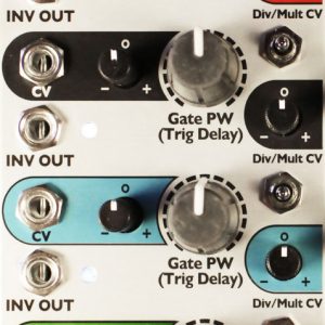
- Interfaces with QCD Expander for more features (Pulse Width, Inverted Gate, attenuverters for CV inputs)
Module size: The QCD is 10HP and 1.57 inches (40mm) deep. All pots have a metal shaft and nut. Power consumption: A jumper selects using +5V from the power supply, or generating +5V on-board from the +12V rail.
- +12V rail: 48mA with jumper selecting external 5V, 88mA with jumper selecting internal 5V.
- +5V rail: 41mA with jumper selecting external 5V, not used (0mA) with jumper selecting internal 5V.
- -12V rail: 40mA


![Ensemble Oscillator [ENOSC]](https://postmodular.co.uk/wp-content/uploads/enosc_front-300x300.jpg)