Dual 12 dB State Variable VCF
£575.00
2 in stock
Description
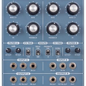
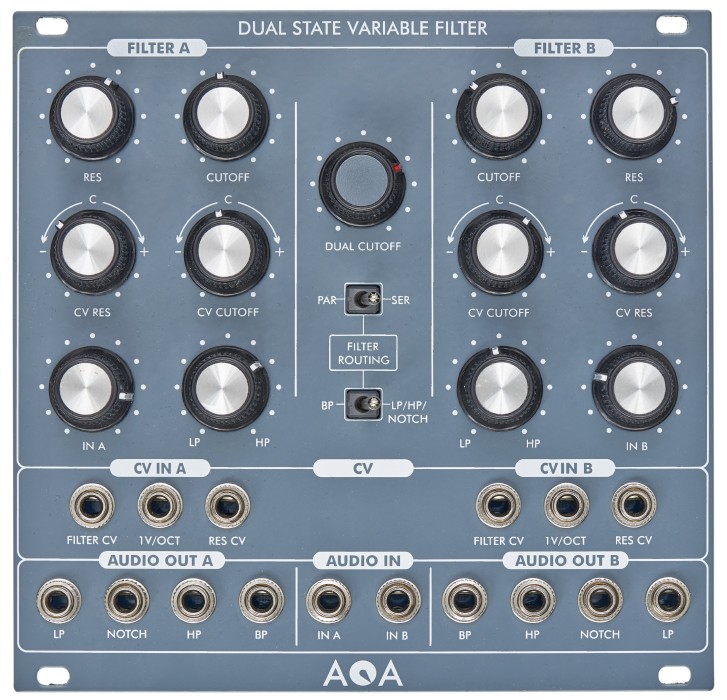
The Dual 12 dB State Variable VCF module contains two 12dB state variable multimode VCF’s A and B, which both offer a Lowpass, a Bandpass and a Highpass filtered output of the input signal as well as a Notch-output, simultaneously.
The notch output is just a crossfaded HP and LP signal, so the corresponding knob can blend continuously between LP (knob fully counterclockwise) over Notch (knobs 12 0’clock position) to HP (knob fully clockwise). Both filters A and B can be independently controlled – there’s a cutoff and a resonance knob for each of them. The cutoff of both filters can also be controlled together by another “main” cut-off knob, so turning that knob, both filter cutoff”s will be controlled in “gang-mode”. All audio and CV inputs are normalized from Filter A=>B. Both filters A and B can be routed in parallel or serial configuration using the “ser/par-switch” ( A=>B or A II B).
Both filters A and B have CV inputs for Cutoff and resonance each, which can be attenuverted separately, so you could use one CV for controlling both filters simultaneously by pluging the control CV into the CV input for filter A, since the CV-inputs are normalized. Both filters could be modulated by the CV in the same direction or in inverse directions by different amounts. Additionally, both filters A and B have an CV input for controlling the cutoff using nearly a Volt/Octave characteristic.
In serial mode, the signal flow is from Filter A=>B. You can use a switch (“HP/LP/Notch/BP”) to select either the LP/Notch/HP-output (choosen by the “LP-HP – knob” of Filter A) or the BP – output of filter A. Both Input – attenuator’s (Filter A and B) are active and can be used to adjust the signal level. Please be careful! The module can produce very loud signals, especially under high resonance settings of both filters and even more, when both cut-off settings of Filter A and B are very close to each other.
Features
- input attenuators for each SVF
- each SVF´s cutoff frequency can be independently controlled by knob
- both cutoff frequencies can be controlled at once with a common cutoff knob
- attenuverted cutoff CV input for each SVF
- each SVF`s resonance can be controlled by knob separately
- each SVF`s resonance can be controlled by an external control voltage individually
- attenuverted resonance CV input for each SVF
- LP/BP/HP Outputs available for each SVF
- variable Balance Notch Output for each SVF (Oberheim SEM)
- 1V/Oct CV Inputs for each SVF
- Routing Mode for each SVF switchable: parallel & serial
- if routed in serial mode, filter type of SVF A selectable (HP…N…LP/BP)
- audio and cv inputs are normalized from SVF B on SVF A
Functions
Audio Input jack SVF A & B – Input for the Audio Signal
Cutoff CV Input jack SVF A & B – CV input for cutoff frequency, attenuverted by CV Cutoff Pot
CV Input jack SVF A & B – CV input for frequency control, attenuated by CV Pot
V/Oct Input jack – CV input for Volt/Octave Range, unattenuated
Measures: 26 TE Power consumption: -12V 50mA / +12V 53mA